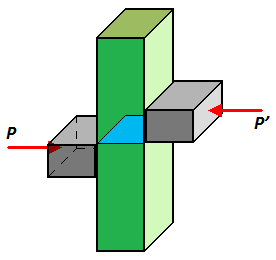
Quick Shear stress is stress parallel to the surface of interest; usually represented by the symbol τ. Shear stress may also be referred to as shearing stress.
The derivations given in the lesson Stresses and Deformations in the Elastic Range were based on the assumption of a homogeneous material with a given modulus of elasticity E. If the member subjected to pure bending is made of two or more materials with different moduli of elasticity, the approache to the determination of the stresses in the member must be modified.
Consider, for instance, a bar consisting of two portions of different materials bonded together as shown in Fig1. This composite bar will deform as described in the lesson Deformations in a Symmetric Member in Pure Bending, since its cross section remains the same throughout its entire length, and since no assumption was made in the lesson Deformations in a Symmetric Member in Pure Bending regarding the stress-strain relationship of the material or materials involved. Thus, the normal strain εx still varies linearly with the distance y from the neutral axis of the section as shown in Fig2 and Fig3, and Eq1 holds:
(Eq1)
εx = −
y
ρ
However, it cannot be assumed that the neutral axis passes through the centroid of the composite section, and one of the goals of the present analysis will be to determine the location of the axis.
Since the moduli of elasticity E1 and E2 of the two materials are different, the expressions obtained for the normal stress in each material will also be different:
(Eq2)
σ1 = E1 εx = −
E1 y
ρ
(Eq3)
σ2 = E2 εx = −
E2 y
ρ
A stress-distribution curve is obtained consisting of two segments of straight line as shown in Fig4. It follows that from Eq2 and Eq3 that the force dF1 exerted on an element of area dA of the upper portion of the cross section is:
(Eq4)
dF1 = σ1 dA = −
E1 y
ρ
dA
while the force dF2 exerted on an element of the same area dA of the lower portion is:
(Eq5)
dF2 = σ2 dA = −
E2 y
ρ
dA
But, denoting by n the ratio E2/E1 of the two moduli of elasticity, dF2 can be expressed as:
(Eq6)
dF2 = −
(nE1 ) y
ρ
dA = −
E1 y
ρ
(n dA)
Comparing Eq4 and Eq6, it is noted that the same force dF2 would be exerted on an element of area n dA of the first material. In other words, the resistance to bending of the bar would remain the same if both portions were made of the first material, provided that the width of each element of the lower portion were multiplied by the factor n. Note that this widening (if n > 1), or narrowing (in n < 1), must be effected in a direction parallel to the neutral axis of the section, since it is essential that the distance y of each element from the neutral axis remain the same. The new cross section obtained in this way is called the transformed section of the member as shown in Fig5.
Since the transformed section represents the cross section of a member made of a homogeneous material with a modulus of elasticity E1, the method described in the less lesson Stresses and Deformations in the Elastic Range can be used to determine the neutral axis of the section and the normal stress at various points of the section. The neutral axis will be drawn through the centroid of the transformed section as shown in Fig6, and the stress σx at any point of the corresponding fictitious homogeneous member will be obtained from Eq7:
(Eq7)
σx = −
My
I
where y is the distance from the neutral surface, and I is the moment of inertia of the transformed section with respect to its centroidal axis.
To obtain the stress σ1 at a point located in the upper portion of the cross section of the original composite bar, the stress σx at the corresponding point of the transformed section is computed. However, to obtain the stress σ2 at a point in the lower portion of the cross section, the stress σx must be multiplied by n where σx is computed at the corresponding point of the transformed section. Instead, as was shown earlier, the same elementary force dF2 is applied to an element of area n dA of the transformed section and to an element of area dA of the original section. Thus, the stress σ2 at a point of the original section must be n times larger than the stress at the corresponding point of the transformed section.
The deformations of a composite member can also be determined by using the transformed section. Recall that the transformed section represents the cross section of a member, made of a homogeneous material of modulus E1, which deforms in the same manner as the composite member. Therefore, using Eq
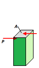
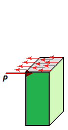
Shear stress is associated with transverse loading. The general equation for shear stress is:
(Eq1)
τave =
P
A
Contrary to normal stress, the distribution of shearing stresses across the section cannot be assumed uniform.
shear stress
transverse loading
Related ▪ L - Difference Between Stress and Strength
▪ L - Stresses on an Oblique Plane Under Axial Loading
▪ L - Average Normal Stress in Solid Member
▪ L - Stresses In A Shaft
▪ L - Transformation of Plane Stress
▪ L - Principle Stresses and Maximum Shear Stress
▪ P - Normal and Shearing Stresses for an Axial Force