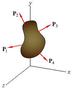
Fig1.
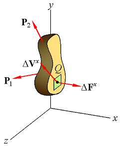
Fig2.
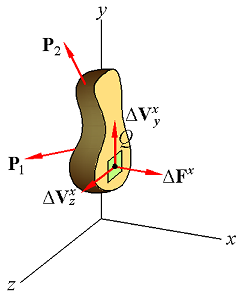
Fig3.
| Stress Under General Loading Conditions and Components of Stress |
Fig1. | Fig2. | Fig3. |
| (Eq1) |
|
| (Eq2) |
|
| (Eq3) |
|
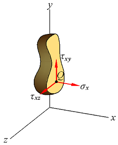 Fig4. | 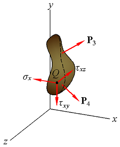 Fig5. |
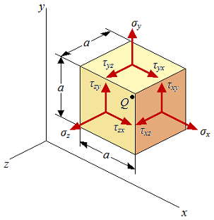 Fig6. | 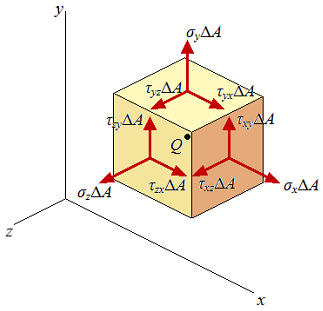 Fig7. |
| (Eq2a) |
|
| (Eq2b) |
|
| (Eq2c) |
|
| (Eq3a) |
|
| (Eq3b) |
|
| (Eq3c) |
|
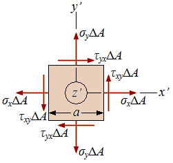 Fig8. |
 ∑Mz = 0: (τxyΔA)a − (τyxΔA)a = 0
| (Eq4a) |
|
| (Eq4b) |
|
| (Eq4c) |
|